Introduction:
The experiment demonstrates how to generate different color patterns using an RGB LED connected to a Raspberry Pi Pico. By adjusting the PWM (Pulse Width Modulation) duty cycle on the RGB pins, we can create a wide range of colors. The PWM signals control the intensity of the Red, Green, and Blue components, thus creating various color combinations.
Scope:
This experiment applies to projects requiring visual feedback or dynamic lighting effects. It is especially useful in embedded systems and IoT applications for status indicators, decorative lighting, or even mood lighting controlled via software.
Prerequisite:
3.1. Hardware:
Pico microcontroller
RGB LED
Resistor (220 ohm)
Breadboard
Jumper wires
USB cable (to connect the computer)
3 .2. Software:
Thonny Software(For micro python)
MicroPython firmware installed on Raspberry Pi Pico
ubuntu Terminal(For embedded C)
CMake,Pico SDK,GNU Arm Embedded Toolchain,WSL.
Connection Details:
Red (R) pin of RGB LED → GPIO 13 (PWM capable pin)
Green (G) pin of RGB LED → GPIO 14 (PWM capable pin)
Blue (B) pin of RGB LED → GPIO 15 (PWM capable pin)
Common Cathode of RGB LED → Ground (GND)
Each color of the RGB LED is connected to a GPIO pin that supports PWM to allow precise control over the intensity of each color component.


Working Principle:
The Raspberry Pi Pico controls the RGB LED using PWM signals on the Red, Green, and Blue pins. By varying the duty cycle (the ratio of the time the signal is "on" vs. the total cycle time), different levels of intensity for each color are achieved. By combining different intensities of Red, Green, and Blue, various color patterns can be generated. The RGB LED's common cathode is connected to the ground, and the PWM signals control the brightness of each color.
PWM:
PWM, or Pulse Width Modulation, is a technique used to control the amount of power delivered to a load without having to vary the voltage or current continuously. It's commonly used in applications like controlling motor speed, dimming LEDs, and generating audio signals.
PWM works by switching a digital signal on and off rapidly. The "on" time is called the pulse width, and by adjusting this pulse width, you can control the average power delivered to a load.
Key Terms:
Frequency:
The frequency of a PWM signal is how often the signal completes one cycle of turning on and off per second. It’s measured in Hertz (Hz). For example, a frequency of 1 kHz means the signal repeats 1000 times per second.
Duty Cycle:
The duty cycle is the percentage of one PWM period in which the signal is "on" (i.e., at a high voltage level).
It’s expressed as a percentage, where:
0% duty cycle means the signal is always off (0V).
50% duty cycle means the signal is on half the time and off half the time.
100% duty cycle means the signal is always on (full voltage).
RGB LED
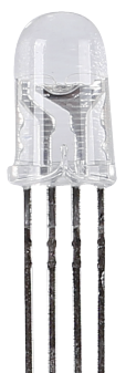
RGB LEDs emit light in various colors. An RGB LED packages three LEDs of red, green, and blue into a transparent or semitransparent plastic shell. It can display various colors by changing the input voltage of the three pins and superimpose them, which, according to statistics, can create 16,777,216 different colors.

RGB LEDs can be categorized into common anode and common cathode ones. In this kit, the latter is used. The common cathode, or CC, means to connect the cathodes of the three LEDs. After you connect it with GND and plug in the three pins, the LED will flash the corresponding color.
Its circuit symbol is shown as figure.
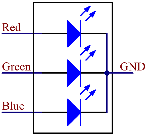
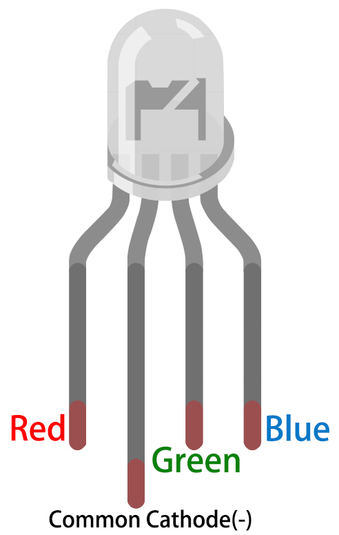
An RGB LED has 4 pins: the longest pin is the common cathode pin, which is usually connected to GND, the left pin next to the longest pin is Red, and the 2 pins on the right are Green and Blue.
Application code:
MicroPython:
import machine
import time
# PWM pins for RGB LED
red_pin = machine.Pin(13)
green_pin = machine.Pin(14)
blue_pin = machine.Pin(15)
# Create PWM objects
red_pwm = machine.PWM(red_pin)
green_pwm = machine.PWM(green_pin)
blue_pwm = machine.PWM(blue_pin)
# Set PWM frequency
red_pwm.freq(1000)
green_pwm.freq(1000)
blue_pwm.freq(1000)
def set_color(red, green, blue):
"""Set the color by adjusting the PWM duty cycle for each channel."""
red_pwm.duty_u16(int(red * 65535))
green_pwm.duty_u16(int(green * 65535))
blue_pwm.duty_u16(int(blue * 65535))
try:
while True:
# Red
set_color(1.0, 0.0, 0.0)
time.sleep(1)
# Green
set_color(0.0, 1.0, 0.0)
time.sleep(1)
# Blue
set_color(0.0, 0.0, 1.0)
time.sleep(1)
# Yellow (Red + Green)
set_color(1.0, 1.0, 0.0)
time.sleep(1)
# Cyan (Green + Blue)
set_color(0.0, 1.0, 1.0)
time.sleep(1)
# Magenta (Red + Blue)
set_color(1.0, 0.0, 1.0)
time.sleep(1)
# White (Red + Green + Blue)
set_color(1.0, 1.0, 1.0)
time.sleep(1)
# Fade in and out (Red)
for i in range(0, 65536, 256):
set_color(i/65535, 0.0, 0.0)
time.sleep(0.01)
for i in range(65535, -1, -256):
set_color(i/65535, 0.0, 0.0)
time.sleep(0.01)
except KeyboardInterrupt:
# Turn off the LED when the program is stopped
set_color(0.0, 0.0, 0.0)
Embedded C:
#include "pico/stdlib.h"
#include "hardware/pwm.h"
// Define the GPIO pins for RGB LED
#define RED_PIN 13
#define GREEN_PIN 14
#define BLUE_PIN 15
// Set PWM wrap value for 16-bit resolution
#define PWM_WRAP 65535
// Function to set up PWM on a GPIO pin
void setup_pwm(uint gpio_pin) {
gpio_set_function(gpio_pin, GPIO_FUNC_PWM);
uint slice_num = pwm_gpio_to_slice_num(gpio_pin);
pwm_set_wrap(slice_num, PWM_WRAP);
pwm_set_enabled(slice_num, true);
}
// Function to set the RGB color by adjusting PWM duty cycle
void set_color(uint red, uint green, uint blue) {
pwm_set_gpio_level(RED_PIN, red);
pwm_set_gpio_level(GREEN_PIN, green);
pwm_set_gpio_level(BLUE_PIN, blue);
}
// Main function
int main() {
stdio_init_all();
// Setup PWM for RGB pins
setup_pwm(RED_PIN);
setup_pwm(GREEN_PIN);
setup_pwm(BLUE_PIN);
while (1) {
// Red
set_color(PWM_WRAP, 0, 0);
sleep_ms(1000);
// Green
set_color(0, PWM_WRAP, 0);
sleep_ms(1000);
// Blue
set_color(0, 0, PWM_WRAP);
sleep_ms(1000);
// Yellow (Red + Green)
set_color(PWM_WRAP, PWM_WRAP, 0);
sleep_ms(1000);
// Cyan (Green + Blue)
set_color(0, PWM_WRAP, PWM_WRAP);
sleep_ms(1000);
// Magenta (Red + Blue)
set_color(PWM_WRAP, 0, PWM_WRAP);
sleep_ms(1000);
// White (Red + Green + Blue)
set_color(PWM_WRAP, PWM_WRAP, PWM_WRAP);
sleep_ms(1000);
// Fade in and out (Red)
for (uint i = 0; i <= PWM_WRAP; i += 256) {
set_color(i, 0, 0); // Fade in red
sleep_ms(10);
}
for (uint i = PWM_WRAP; i != (uint)-1; i -= 256) {
set_color(i, 0, 0); // Fade out red
sleep_ms(10);
}
}
return 0;
}
Hardware Image:

Output:
The output will be a smoothly transitioning series of color patterns displayed by the RGB LED. The brightness of Red, Green, and Blue components will vary according to the PWM duty cycle, producing different color combinations.
Video Demonstration:
Appendix:
Common CMakeLists:
cmake_minimum_required(VERSION 3.12)
# Pull in SDK (must be before project)
include(pico_sdk_import.cmake)
project(pico_experiments C CXX ASM)
set(CMAKE_C_STANDARD 11)
set(CMAKE_CXX_STANDARD 17)
if (PICO_SDK_VERSION_STRING VERSION_LESS "1.3.0")
message(FATAL_ERROR "Raspberry Pi Pico SDK version 1.3.0 (or later) required. Your version is ${PICO_SDK_VERSION_STRING}")
endif()
# Initialize the SDK
pico_sdk_init()
add_compile_options(-Wall
-Wno-format # int != int32_t as far as the compiler is concerned because gcc has int32_t as long int
-Wno-unused-function # we have some for the docs that arent called
)
if (CMAKE_C_COMPILER_ID STREQUAL "GNU")
add_compile_options(-Wno-maybe-uninitialized)
endif()
# Hardware-specific examples in subdirectories:
add_subdirectory(expt_10_LCD)
CMakeLists:
cmake_minimum_required(VERSION 3.13)
include(pico_sdk_import.cmake)
project(rgb_led)
pico_sdk_init()
add_executable(rgb_led main.c)
target_link_libraries(rgb_led pico_stdlib hardware_pwm)
pico_enable_stdio_usb(rgb_led 1)
pico_enable_stdio_uart(rgb_led 0)
pico_add_extra_outputs(rgb_led)
References:
develop, and troubleshoot embedded C programs on
| # | Topic | Date & time | Action |
|---|
0% Completed (0/1)